A-1.7 Describe Lockout and Tag-out (LOTO) Procedures
Lockout and tag-out (LOTO) procedures are essential safety practices that help prevent injuries when working on machinery or piping systems. They ensure that all sources of hazardous energy are identified, isolated, and controlled before maintenance or repair work begins. Understanding how and why LOTO procedures are performed helps workers protect themselves and others from unexpected equipment movement or the release of stored energy.
Understanding System Operation
When performing maintenance or repair work, or when a machine is unsafe, it is critical to prevent the machine from moving or releasing energy unexpectedly. Lockout and tag-out (LOTO) procedures are used to control these hazards by identifying and isolating all sources of energy before work begins.
Simply turning off power or closing a valve may not be enough. Some systems store energy, such as electrical charge, pressure, or fluid, which must be released or tested before the equipment is safe. For example, pressurized piping must be fully depressurized before work starts.
Once equipment has been properly locked out and tagged out, it should be in a zero-energy state. Never assume equipment is safe—always test or verify that all energy has been removed before starting work.
Before applying any lockout procedure, workers must fully understand the system they are working on and the tasks being performed.
WorkSafeBC Regulations and Lockouts
De-energization and lockout procedures are described in Part 10: De-energization and Lockout of the OHS Regulation.
Note the following:
- You must use your own locks and keys.
- You must not borrow another person’s lock. If necessary, get extra locks from your supervisor.
- You must remove your own locks.
- You must not remove someone else’s lock.
- If you apply the first lock, you must ensure that the machinery cannot be operated.
- In an emergency, a senior shift supervisor may remove someone else’s lock, but only after every effort has been made to contact the person who put on the lock. The supervisor must ensure that the equipment will operate safely.
Identification Requirements
The following items must be identified and acted on as part of a lockout procedure:
- Identify all energy sources that influence or are connected to the machinery or equipment.
- Identify the correct electrical source and disconnect it in the following way:
- For plugged-in equipment, pull the plug from the socket, and place the male end on the equipment where it is readily visible.
- Identify the correct breaker and switch it to the off position.
- Identify the equipment to be shut down.
- Identify the correct switch and turn it to the off position.
Situations Where Lockout is Required
Depending on the type of machine involved, in addition to electrical power, you must consider the following sources of energy:
- Hydraulic fluids under pressure
- Compressed air or gases
- Energy stored in springs
- Potential energy from suspended parts
- Electrical components that hold a charge
- Any other source that might cause mechanical movement
Lockout Equipment
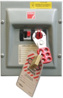
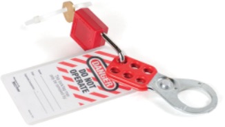
There are many different types of locking systems. Put your personal lock on the switch using a scissor adapter or hasp, as shown in Figure 1. While this figure shows a single safety hasp and lock, it is also common to use more than one hasp when locking out.
Chains and Cables
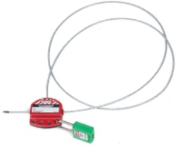
If you need to lock out equipment with more than one energy source, you can use a lockout cable instead of several individual locks to secure multiple disconnect switches (Figure 2). Run the cable through the locking hole of each safety disconnect being locked out. The cable diameter must be large enough to prevent the safety disconnect switches from being operated accidentally. A scissor lock adapter may also be used to apply multiple locks.
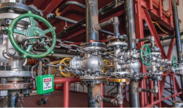
Chains and cables can also be used be used to make valve handles inoperable (Figure 3).
Support Blocks
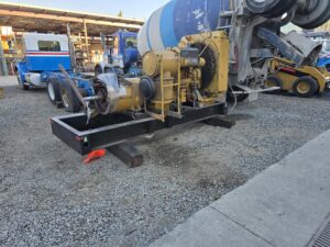
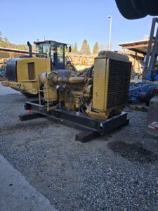
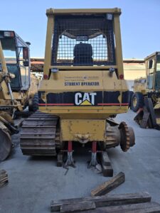
Support blocks are physical devices used to secure equipment and prevent unintended movement, lowering, or shifting during maintenance or storage. These may include solid wood cribbing, engineered blocking systems, or adjustable support stands. Blocks must always be placed on stable, level ground and positioned to evenly distribute the load. When properly installed, they act as a critical secondary support in case of mechanical failure.
Never place any part of your body beneath suspended equipment or between a block and the equipment, as shifting or collapse can occur without warning.
Tags, Locks and Scissors
Lockout devices must provide a visual verification, must be locked as required, and must have a “DO NOT OPERATE” tag placed on them. The tag must have on it your name, the date and time, and the location and identity of the equipment being worked on. Combination locks are not to be used for locking out equipment.
Lockout for Circuit Breakers
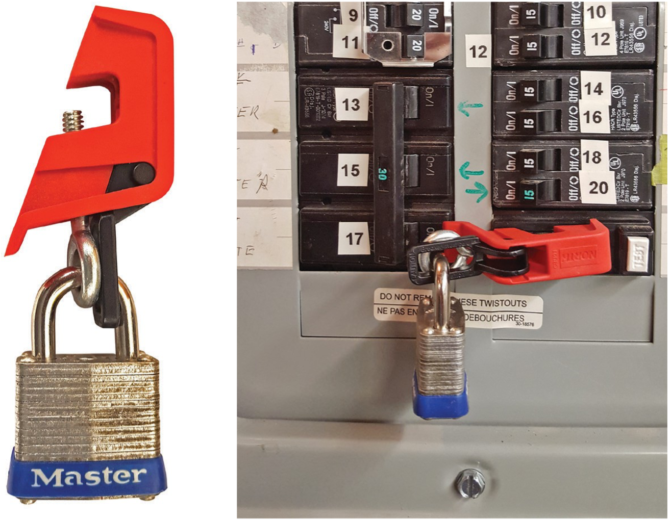
Lock out the desired breaker. If there is access to the main breaker or disconnect that kills all power to the panel, and if no other workers need to lock out in that panel, then you may lock the panel door closed (Figure 5).
Cord Locks
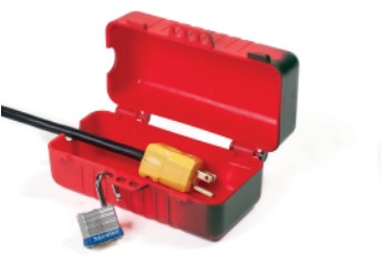
For plugged-in equipment, if the male end of the plug is in view and you do not leave the machine until you have finished working, a lock is not needed. If the plug is not in view, use an adapter and lock, or lock the cord to an object to prevent it from being reconnected to the circuit. Figure 6 shows a power cord plug lock.
Lockout Station
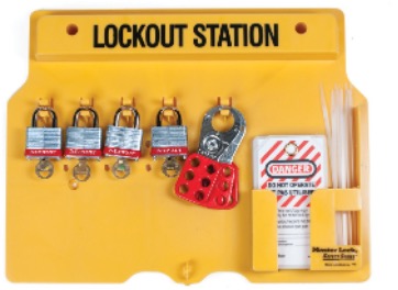
A lockout station has keyed locks to be used only for equipment lockout. It also contains tags and lockout devices. Locks have one key that is kept with the installer of the lock. Once the work procedure is completed, the lock and key should be returned to the lockout station. These stations can be portable or mounted permanently to the wall where required.
Key Box System
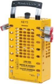
Some machines are powered by multiple energy sources, so a single job may require locking out several controls at once. This can be managed efficiently and safely using a key box system. In this system, each energy-isolating device is locked with its own lock (Lock Set A). The keys for those locks are then placed inside a locked key box, which is secured with a second set of locks (Lock Set B). Each worker involved attaches their personal lock to the key box to ensure the equipment cannot be re-energized until all workers have removed their locks. The key box itself is treated as a locked-out power source, and all lockout regulations apply. A key box lockout procedure checklist must be posted nearby to guide workers through the process.
Spades and Blinds
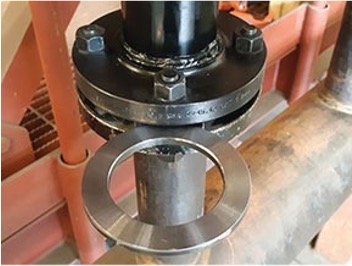
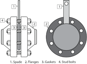
In the context of lockout, a spade is a round plate with a small tab that is placed between two pipe flanges in order to lock out certain piping sections. It is sometimes referred to as a frying pan (see Figure 12). The spade prevents cross-contamination and also allows work to be done on individual piping sections. The small tab lets workers see that the spade is in place, in the same way an indicator valve allows workers see whether a valve is in the open or closed position.
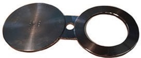
A spectacle blind, or spectacle flange, is two discs joined together resembling a pair of spectacles. These can be rotated in place, allowing flow through the opening in one of the discs or blocking the flange with the solid disc.
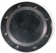
A blind flange (Figure 13) is used when the end of the pipe or valve is removed. An open flange can be closed off with a blind flange.
 Self-Test A-1.7: Describe Lockout and Tagout Procedures
Complete Self-Test A-1.7 and check your answers.
If you are using a printed copy, please find Self-Test A-1.7 and Answer Key at the end of this section. If you prefer, you can scan the QR code with your digital device to go directly to the interactive Self-Test.
References
BC Industry Training Authority. (2019). Piping trades apprenticeship program: Perform safety related functions—Level 1 harmonized [Binder]. Crown Publications, Queen’s Printer for British Columbia. https://www.crownpub.bc.ca/Product/Details/7960000260_S
Camosun College. (2019). Line A: Safe work practices—Competency A-1: Control workplace hazards (Rev. ed.) [Learning guide]. BCcampus. https://collection.bccampus.ca/textbook/tQtm8KNK/
Camosun College. (2015). Trades Access Common Core Competency A-1: Control Workplace Hazards. Victoria, B.C.: Crown Publications. Download for free from the B.C. Open Textbook Collection (https://open.bccampus.ca/browse-ourcollection/find-open-textbooks/).
WorkSafeBC. (n.d.). OHS Regulation Part 10: De-energization and lockout. https://www.worksafebc.com/en/law-policy/occupational-health-safety/searchable-ohs-regulation/ohs-regulation/part-10-de-energization-and-lockout
Media Attributions
All figures are sourced from Industry Training Authority (2019) and/or Camosun College (2019) and are used under the Creative Commons Attribution 4.0 (CC BY 4.0) licence unless otherwise noted. Images copyrighted by the BC Industry Training Authority are licensed under a Creative Commons Attribution-NonCommercial-ShareAlike 4.0 (CC BY-NC-SA 4.0) licence.
- Figure 4a, 4b and 4c Support blocks are by Audrey Curran, Thompson Rivers University, and is subject to the CC BY-NC-SA 4.0 license of this resource.
A round plate with a small tab that is placed between two pipe flanges in order to lock out certain piping sections.
A metal safety device placed between pipe flanges to stop liquid or gas from flowing through a pipe. It has one solid side that blocks the pipe and one open side that allows flow. Turning it to the solid side makes the pipe safe to work on by fully blocking the flow.
A solid metal plate bolted to the end of a pipe to completely block the flow of liquid or gas, making the pipe safe to work on.
The end of a pipe where the flange is not covered or sealed, allowing liquid or gas to flow through the pipe.